MEL TECH
CIRCTRONICS
Mesh Analysis
The Mesh Current Method, also known as the Loop Current Method, is quite similar to the Branch Current method in that it uses simultaneous equations, Kirchhoff's Voltage Law, and Ohm's Law to determine unknown currents in a network. It differs from the Branch Current method in that it does not use Kirchhoff's Current Law, and it is usually able to solve a circuit with less unknown variables and less simultaneous equations, which is especially nice if you're forced to solve without a calculator.

The first step in the Mesh Current method is to identify “loops” within the circuit encompassing all components. In our example circuit, the loop formed by B1, R1, and R2 will be the first while the loop formed by B2, R2, and R3 will be the second. The strangest part of the Mesh Current method is envisioning circulating currents in each of the loops. In fact, this method gets its name from the idea of these currents meshing together between loops like sets of spinning gears:

The choice of each current's direction is entirely arbitrary, just as in the Branch Current method, but the resulting equations are easier to solve if the currents are going the same direction through intersecting components (note how currents I1 and I2 are both going “up” through resistor R2, where they “mesh,” or intersect). If the assumed direction of a mesh current is wrong, the answer for that current will have a negative value.
The next step is to label all voltage drop polarities across resistors according to the assumed directions of the mesh currents. Remember that the “upstream” end of a resistor will always be negative, and the “downstream” end of a resistor positive with respect to each other, since electrons are negatively charged. The battery polarities, of course, are dictated by their symbol orientations in the diagram, and may or may not “agree” with the resistor polarities (assumed current directions):

Using Kirchhoff's Voltage Law, we can now step around each of these loops, generating equations representative of the component voltage drops and polarities. As with the Branch Current method, we will denote a resistor's voltage drop as the product of the resistance (in ohms) and its respective mesh current (that quantity being unknown at this point). Where two currents mesh together, we will write that term in the equation with resistor current being the sum of the two meshing currents.
Tracing the left loop of the circuit, starting from the upper-left corner and moving counter-clockwise (the choice of starting points and directions is ultimately irrelevant), counting polarity as if we had a voltmeter in hand, red lead on the point ahead and black lead on the point behind, we get this equation:
-28 + 2 (I1 - I2) + 4I1 = 0
Notice that the middle term of the equation uses the sum of mesh currents I1 and I2 as the current through resistor R2. This is because mesh currents I1 and I2 are going the same direction through R2, and thus complement each other. Distributing the coefficient of 2 to the I1 and I2 terms, and then combining I1 terms in the equation, we can simplify as such:
-28 + 2 (I1 - I2) + 4I1 = 0 Original Form of Equation
..Distributing to terms within parenthesis..
-28 + 2I1+ 2I2 + 4I1 = 0
..Combining like terms..
-28 + 6I1 + 2I2 = 0 Simplified Form of Equation
At this time we have one equation with two unknowns. To be able to solve for two unknown mesh currents, we must have two equations. If we trace the other loop of the circuit, we can obtain another KVL equation and have enough data to solve for the two currents. Creature of habit that I am, I'll start at the upper-left hand corner of the right loop and trace counter-clockwise:
-2 (I1 +I2) +7 - 1I2 = 0
Simplifying the equation as before, we end up with:
-2I1 - 3I2 +7 = 0
Now, with two equations, we can use one of several methods to mathematically solve for the unknown currents I1 and I2:
-28 + 6I1 + 2I2 = 0
-2I1 - 3I2 + 7 = 0
..rearranging equation for easier equation..
6I1 + 2I2 = -28
-2I1 - 3I2 = -7
Solutions:
I1 = 5 A
I2 = -1 A
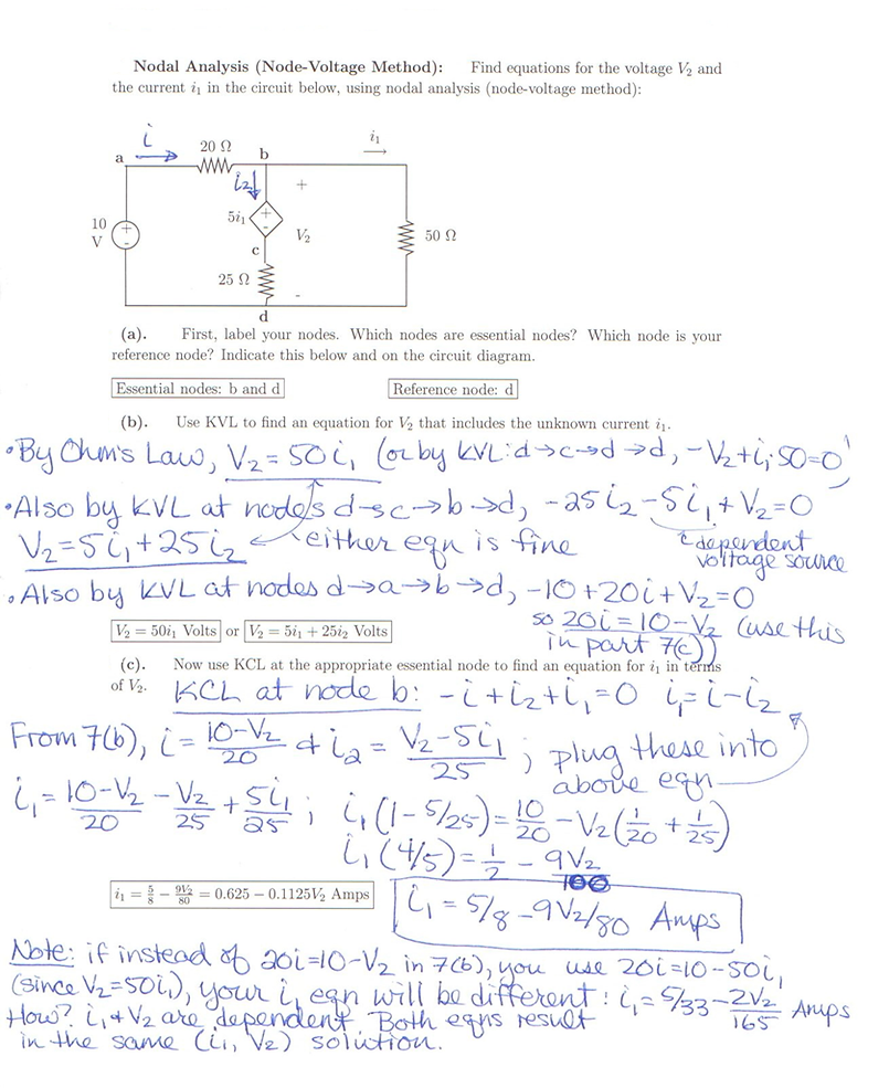
Nodal Analysis
In electric circuits analysis, nodal analysis, node-voltage analysis, or the branch current method is a method of determining the voltage (potential difference) between "nodes" (points where elements or branches connect) in an electrical circuit in terms of the branch currents.
Method
-
Note all connected wire segments in the circuit. These are the nodes of nodal analysis.
-
Select one node as the ground reference. The choice does not affect the result and is just a matter of convention. Choosing the node with the most connections can simplify the analysis.
-
Assign a variable for each node whose voltage is unknown. If the voltage is already known, it is not necessary to assign a variable.
-
For each unknown voltage, form an equation based on Kirchhoff's current law. Basically, add together all currents leaving from the node and mark the sum equal to zero. Finding the current between two nodes is nothing more than "the node you're on, minus the node you're going to, divided by the resistance between the two nodes."
-
If there are voltage sources between two unknown voltages, join the two nodes as a supernode. The currents of the two nodes are combined in a single equation, and a new equation for the voltages is formed.
-
Solve the system of simultaneous equations for each unknown voltage.
Example: