
MEL TECH
CIRCTRONICS
Project - Line Follower Mobot using PIC 16F877A
OBJECTIVES:
-
To design a line following mobile robot for multipurpose application with a suitable body and wheel robot.
-
To implement programmable software to be cooperating with the PIC. This project using PIC16F877A microcontroller as the controller.
-
To achieve smooth motion using the sensor and motor combination.
-
To build mechanical structure that suitable and can perform efficiently.
MATERIALS:
-
(1) LM324 – operational amplifiers
-
(1) L298 – H-Bridge (IC)
-
(3) CNY70 – optocoupler sensors
-
(1) PIC877A – microprocessor
-
(1) Trimmer/potentiometer – adjustable resistor
-
(1) LM7805 or LM323 or any regulators that has 3A rating and adjust the voltage to 5V. (I suggest to use LM323 it has a 3A current rating)
-
Resistors and capacitors
-
(1) Crystal oscillator – 20MHz
-
(10) Header pins
-
Wires (either solid or stranded)
-
(1) RC car
SPECIFICATIONS:
-
The system is based on a sports car Chassis.
-
Propulsion is provided by two geared 6-Volt DC motors.
-
Two DC motors drive wheels moving forward, left or right direction.
-
Power is provided by 8 AA-size 1.5-Volt Batteries (13.5V nominal voltage).
-
Voltage is regulated to motors with a 9-Volt regulator and a 1000µF capacitor.
-
The PIC16F877A regulates voltage to peripherals with its onboard voltage regulator.
-
The robot follows a black line on a white surface.
-
Line sensing is accomplished by an infrared IR reflectance sensor array.
-
When the infrared signal falls on the white surface, it gets reflected and if it falls on the black surface, it is not reflected.
-
The robot is controlled by a PIC16F877A microcontroller.
-
The Microcontroller PIC16F877A is used to control the motors. It gets the signals from the infrared sensors and it drives the motors according to the sensor inputs.
-
The program is written in MPLab programming language (C/C++).
-
Color is distinguished using a supplied color sensor to distinguish white and black.
-
Black lines are detected with an IR Sensor.
-
Inputs are connected to the PIC16F877A through a PICkit or PIC loader.
PROCEDURE:
-
The first step is to determine what your mobot should do. (My mobot’s goal is to follow a black line on a white surface).
-
Now, it is time to decide on what design of mobot you are going to build. A custom robot design often starts with a “vision” of what the mobot will look like and what it will do.
-
Then, choose a microcontroller which you want to use. (My microcontroller is PIC16F877A).
-
Create or look for a circuit diagram of your mobot.
-
Now, purchase the materials needed. (We ordered at the e-gizmo since some of the materials are not available here in Gensan).
-
Purchase also an RC car for your chassis. Buy the one that has the remote control, because the DC motor of it is the one that you are going to use.
-
Create a PCB layout of your circuit for etching. Using Proteus, we create the circuit first if it is really functioning then convert it into PCB layout then edit.
-
Print the final PCB layout using photo paper and etch it to the PCB using ferric chloride.
-
After etching, test the connection of each line. (For security purposes).
-
Now, drill the PCB. Drill only the part that is intended to drill.
-
Solder the materials one by one. Be careful not to connect the other which are not really connected this may cause short circuit and it has a very big impact.
-
After soldering all of them, place your PIC16F877A to the PIC socket and connect it to the PICkit 2 for programming. The PICkit 2 will be connected to your desktop or laptop.
-
Using MPLab IDE, make sure that your program is ready. Load your microcontroller.
-
After loading, test the three sensors (left, center and right side) using your CNY70. If the sensors are functioning well, proceed to the next step.
-
Now, place your circuit together with the microcontroller to your chassis.
-
Check the connections between circuit and DC motor. Be careful with the polarities. Positive is for positive and negative is for negative.
-
Test the wheels of your chassis if it is turning left and right. If it is functioning well, proceed to the next step.
-
Make also a bumper where you will place your sensors.
-
Now, you can finally make your own design. Be creative!
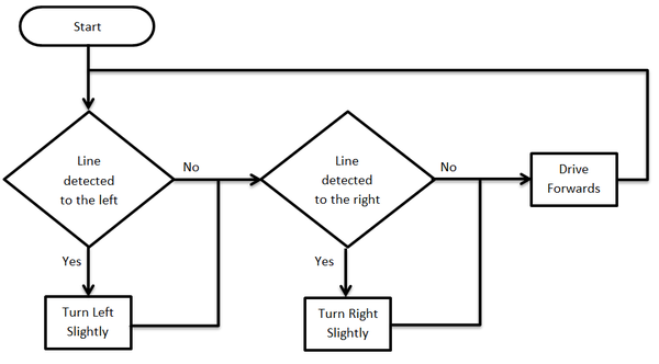
FLOWCHART:
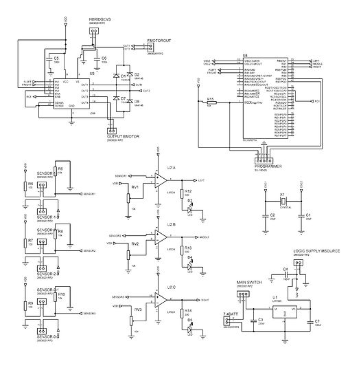
SCHEMATIC DIAGRAM:
CODES:
// HARDWARE:
// - PIC16F877A, 20MHz High Speed Oscillator
// - Oscillscope probe --> RC2/CCP1 (PWM1)
// - Oscillscope probe --> RC1/CCP2 (PWM2)
/*
*/
#include <pic.h>
//SENSOR
//#define RIGHT RB0
//#define MIDDLE RB1
//#define LEFT RB2
#define RIGHT RB2
#define MIDDLE RB1
#define LEFT RB0
#define STOPPER RA2
//Configuration bits
__CONFIG(HS & WDTDIS & PWRTDIS & UNPROTECT & LVPDIS);
//Defines
#define normal 0b11000111 //PWM2 Duty Cycle = 90
#define slow 0b10101110 /*value here (PWM Duty Cycle = 80%)*/
#define slowest 0b10101110 /*value here (PWM Duty Cyle= 70%)*/
//Function Prototypes
void PWMInit(void);
unsigned int a=0;
void main()
{
TRISB = 0x0F;
TRISA = 0b00000100;
ADCON1 = 0x06;
PWMInit();
while(1)
{
if(RA2==1)
{
if(LEFT == 1 && MIDDLE == 0 && RIGHT == 1)
{
RA0 = 0;RA1 = 0;CCPR2L=normal;
}
else if(LEFT == 0 && MIDDLE == 0 && RIGHT == 1)
{
RA0 = 1;RA1 = 0;CCPR2L=slow;
}
else if(LEFT == 1 && MIDDLE == 0 && RIGHT == 0)
{
RA0 = 0;RA1 = 1;CCPR2L=slow;
}
else if(LEFT == 0 && MIDDLE == 1 && RIGHT == 1)
{
RA0 = 1;RA1 = 0;CCPR2L=slowest;
}
else if(LEFT == 1 && MIDDLE == 1 && RIGHT == 0)
{
RA0 = 0;RA1 = 1;CCPR2L=slowest;
}
}
else if(RA2==0)
{
CCPR2L=0;
}
}
}
/*----------------------------------------------------------------
PWM PROGRAMMING
----------------------------------------------------------------*/
//Initialize CCP1 & CCP2 for PWM Operation
void PWMInit(void)
{
TMR2 = 0x00; //Clear TMR2 & CPP related registers
T2CON = 0x00;
CCP1CON = 0x00;
CCP2CON = 0x00;
PR2 = 249; //Set PWM freq = 5Khz
CCPR2L = normal; //Set PWM2 Duty Cycle
TRISC1 = 0; //Enable PWM2 output pin
T2CKPS1 = 0; //Prescaler = 4
T2CKPS0 = 1;
CCP2CON = 0x0C; //CCP2 in PWM mode
TMR2ON = 1; //Enable TMR2. PWM signal is generated.
return;
}
- ENJOY! -